Research and development · 2022
CoSoX — Collettore Solare X
More yield from the same photovoltaic panels, by enclosing them in a collector with mirrored surfaces. The CoSimX simulator written from scratch, 3D-printed scale prototypes, validation measurements in the lab.
Official title: «CoSoX — Collettore Solare X: testing collectors with reflective surfaces to improve the yield of standard photovoltaic panels».
Goal
CoSoX (Collettore Solare X) was born to test ways of improving the yield of standard solar panels, polycrystalline and monocrystalline, by placing them in a container with mirrored surfaces and varying their arrangement. The goals: reduce the surface needed for the same output, or reduce the number of panels for the same output.
What was done
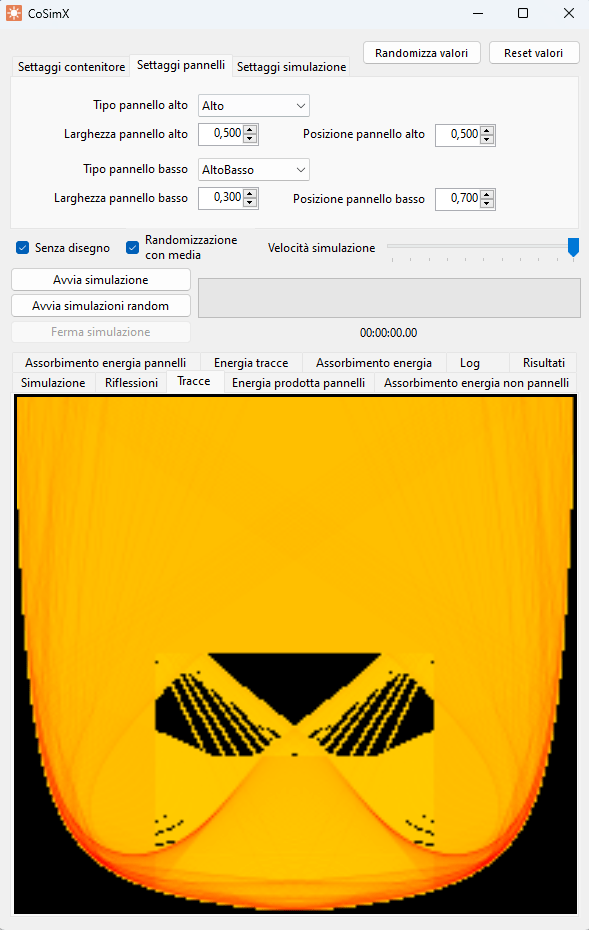
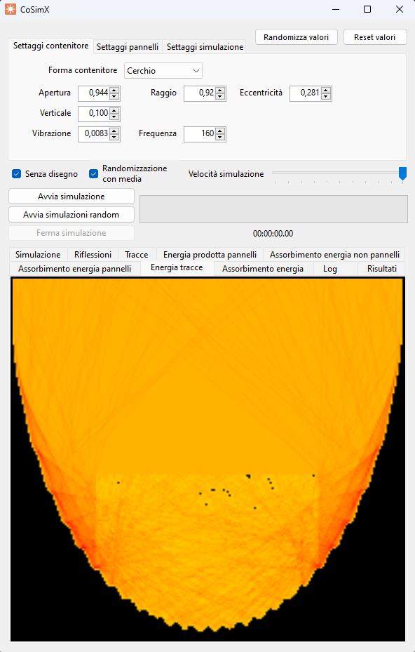
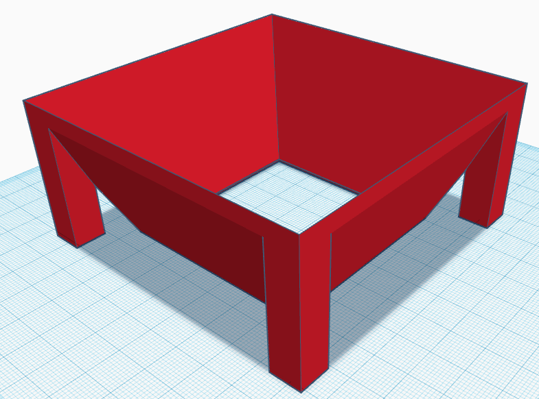
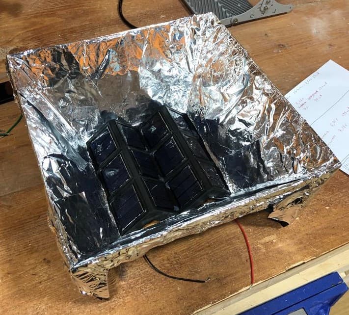
The work started with the construction, from scratch, of a software simulator, christened CoSimX (C# on .NET Framework, Windows environment), which simulates the absorption and reflection of the radiation in the container as the geometry — parabola, circle, sine, hyperbola —, the positioning and the efficiency parameters vary, with a randomisation function to explore the most promising configurations automatically. The chosen geometry, the simplest to build mechanically, is a truncated pyramid with a square base and reflective walls concentrating the light onto the panels.
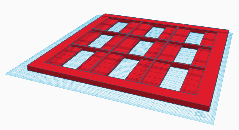
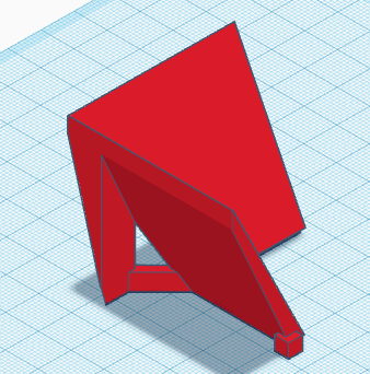
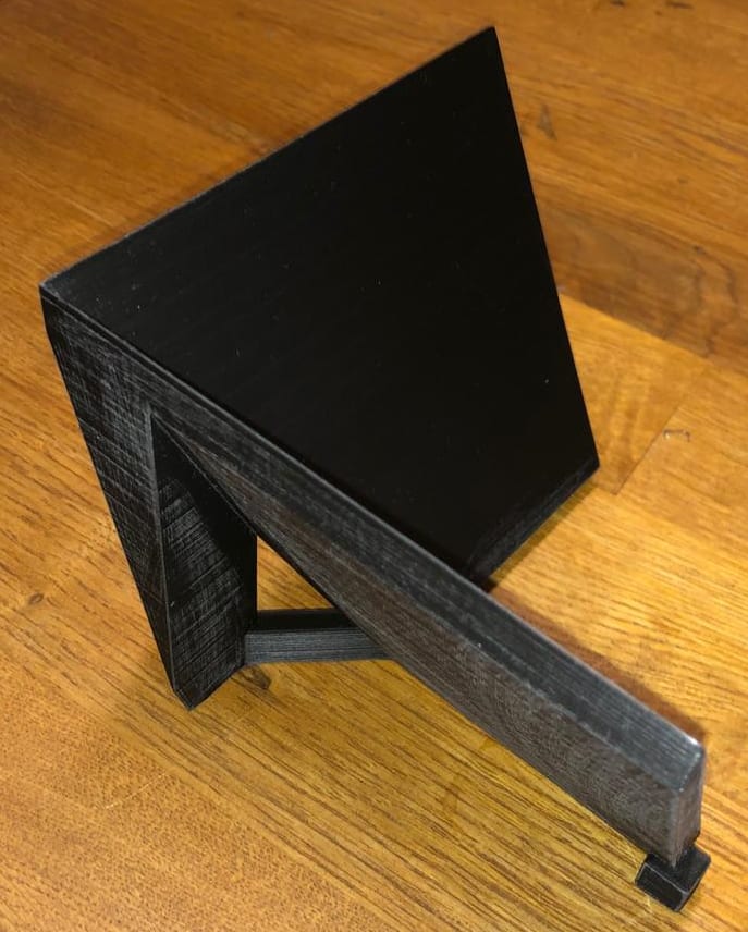
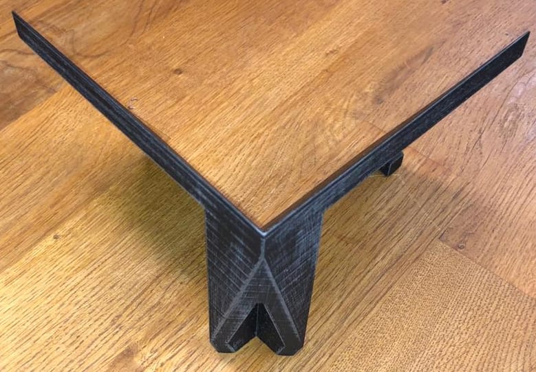
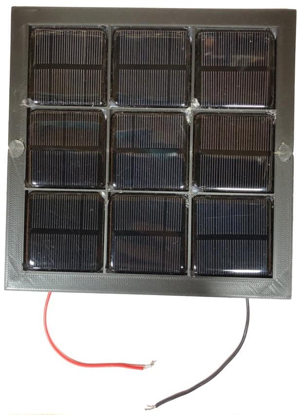
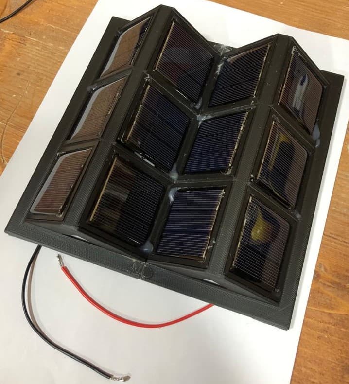
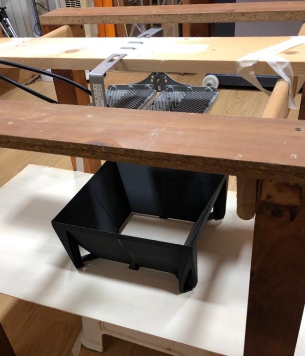
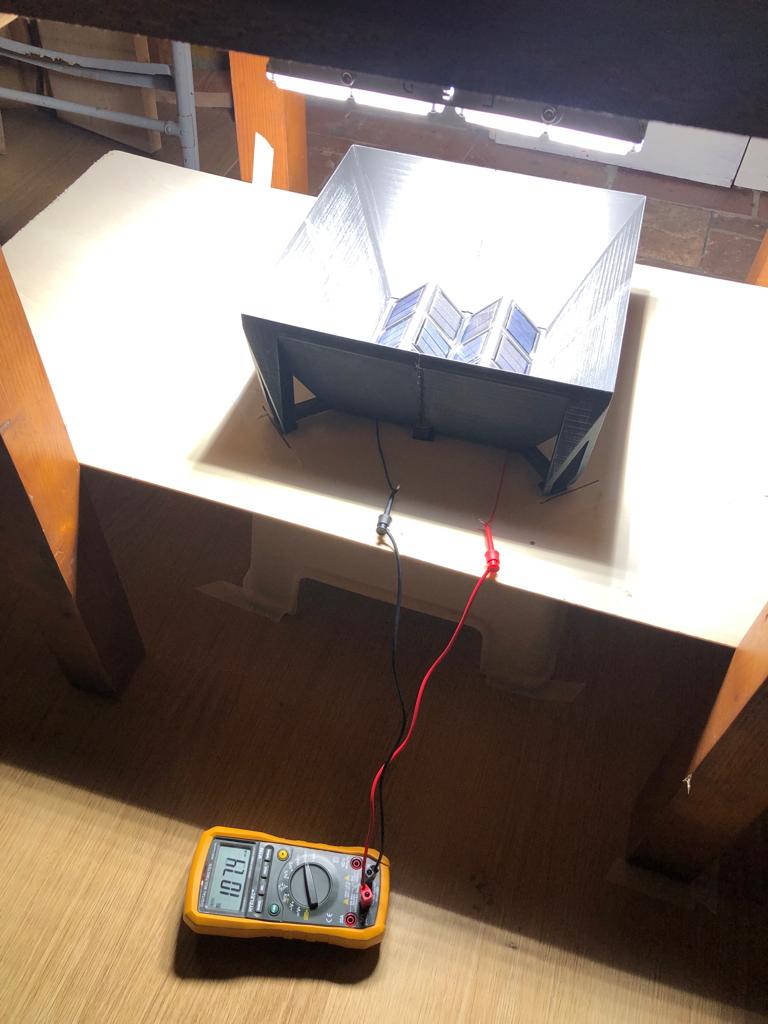
The scale prototypes were modelled in CAD and 3D-printed in high-temperature-resistant PLA, with two mounting configurations compared: a flat 3x3 matrix and an angled 4x3 configuration, with 45-degree incidence. Measurements were taken on a test bench with three 100 W LED floodlights powered by a UPS, in two separate sessions for a total of 16 measurements over 8 configurations: mono- and polycrystalline panels, flat and angled, with and without aluminium reflective surfaces.
What came of it
The angled configurations proved disadvantageous every time, while the reflective container gave an average gain of 60-70% over the non-reflective configuration: for the same overall footprint, every square metre of panels in a reflective collector yields as much as 1.60-1.70 square metres of bare panels. Of the two initial goals, then, the reduction in the number of panels was achieved, at the expense of the surface occupied; the report indicates the most promising configuration — flat monocrystalline panels in a reflective container — and the directions for taking the research further.
From the lab
The images come from the project’s original documentation.