Research and development · 2021
WAIP — AI Powered WorkBench
A workbench that projects instructions onto the surface and recognises the position of the operator's hands: it guides assembly and measures times and progress. Computer vision on a stereo camera, working prototype.
Official title: «WAIP — AI Powered WorkBench: a workbench assisted by artificial intelligence, with projected information and hand-position recognition».
Goal
WAIP (AI Powered WorkBench) is the idea of a new generation of workbench: a system which, through information projected directly onto the work surface and recognition of the position of the hands, supports the operator in building, assembling and repairing — and at the same time tracks progress, with statistics on times and photos of each phase.
It’s the project that marks a date: computer vision applied to manual work, here, is from 2021. We didn’t ride the 2023 wave to get to AI — we were already working on it.
What was done
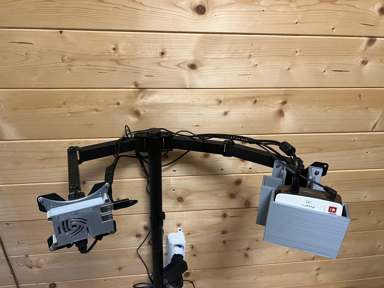
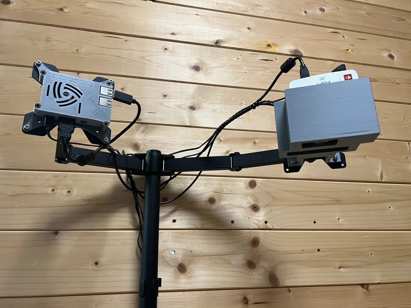
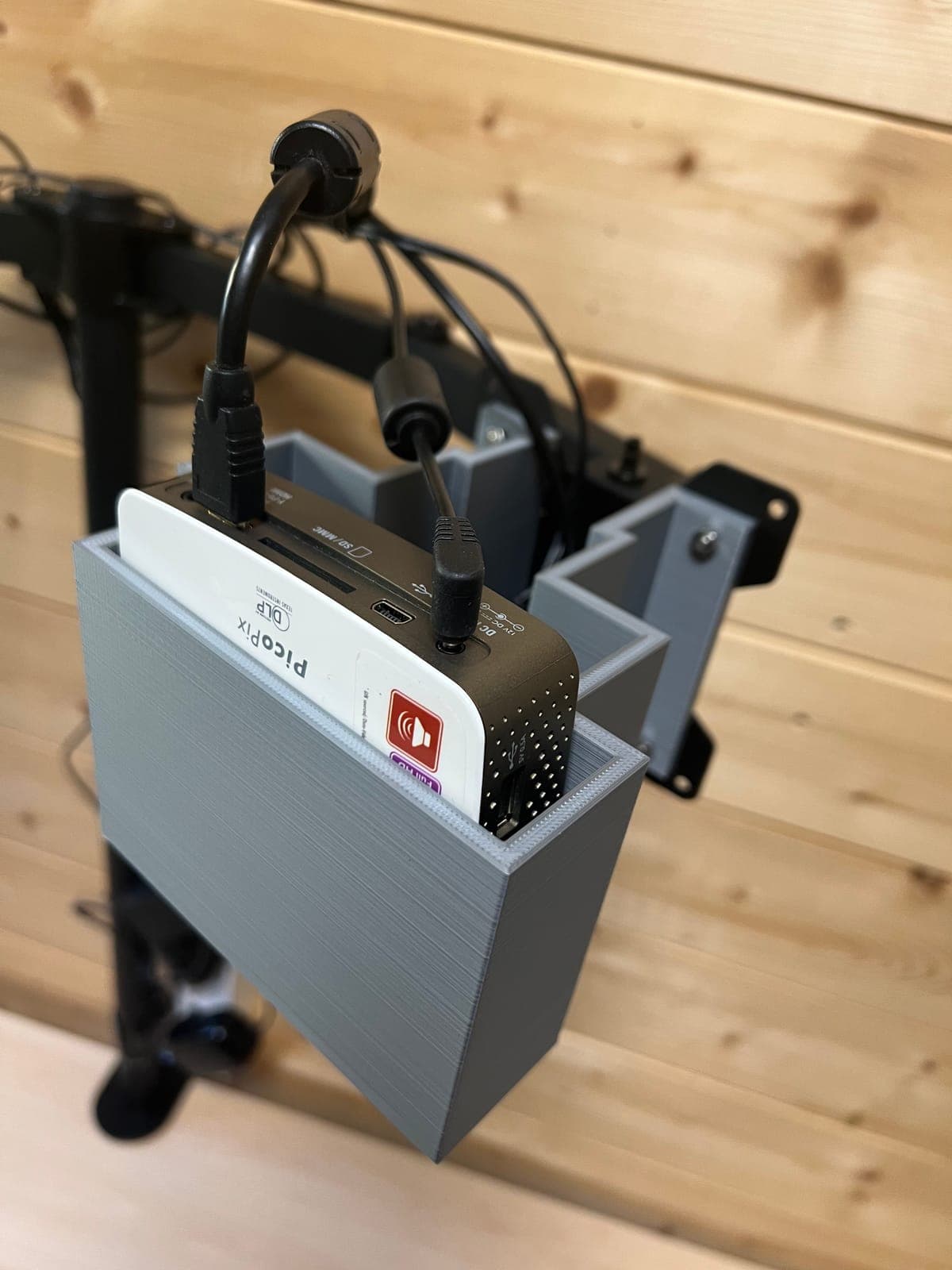
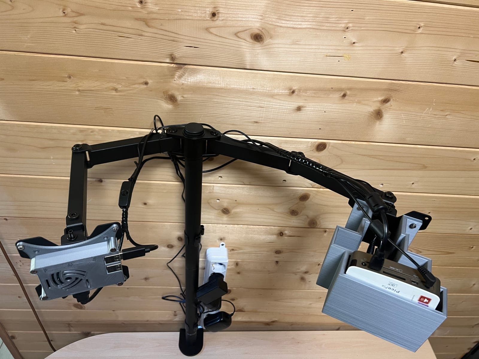
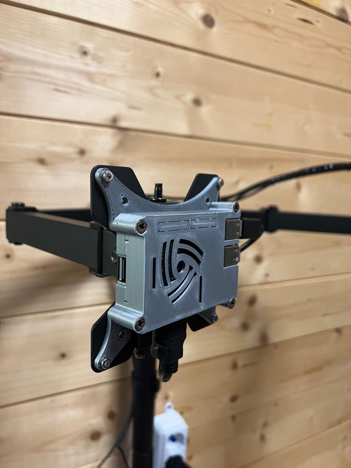
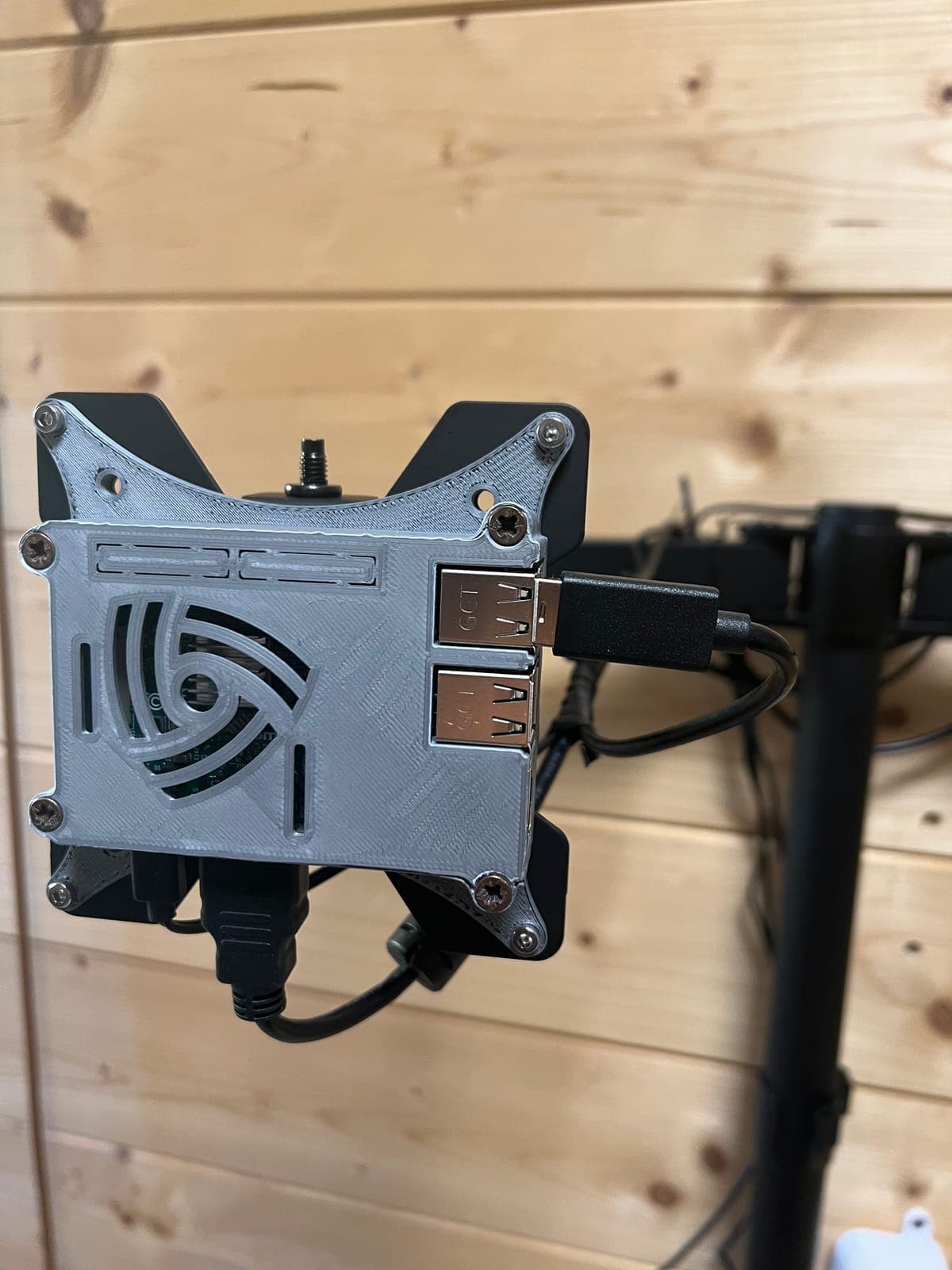
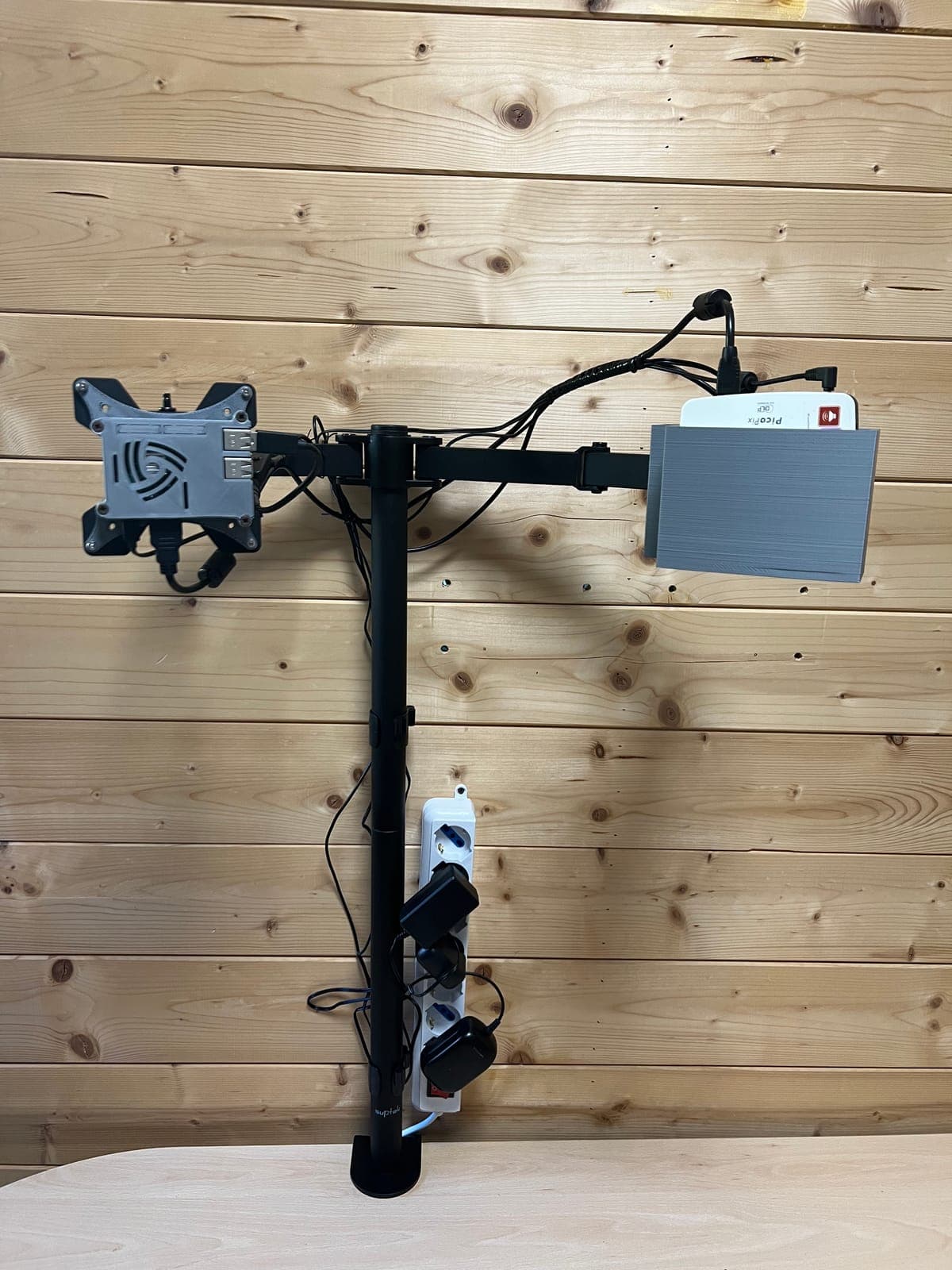
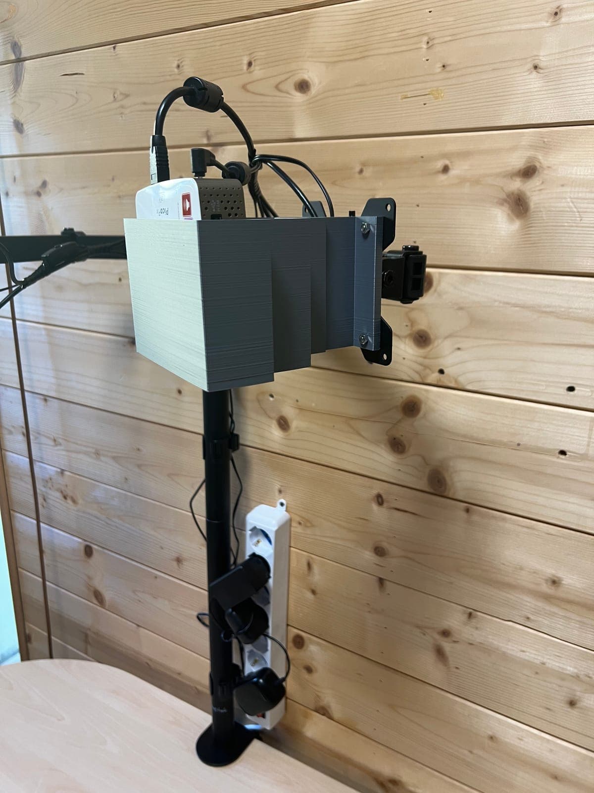
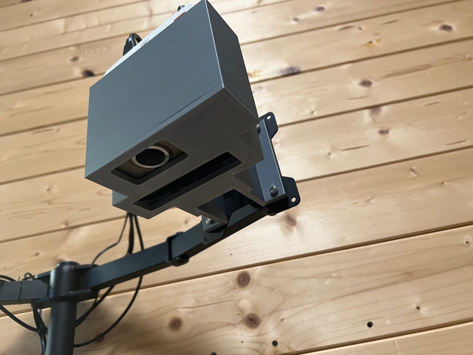
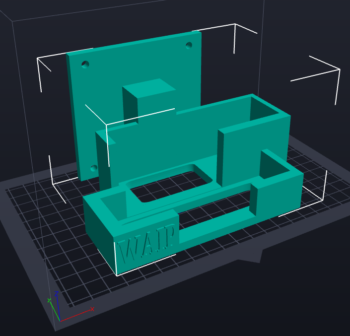
The hardware prototype joins a Luxonis OAK-D AI camera — processing up to 4 TOPS, stereo vision with depth perception, 2D and 3D object tracking —, a compact Philips PicoPix projector and a Raspberry Pi 3B as the processing unit, mounted on an arm structure above the bench. To keep the parts aligned, the physical mounts for the components were modelled and 3D-printed. The software was developed in Python, with an interface built on the Kivy framework, first on Windows and then ported to the Raspberry.
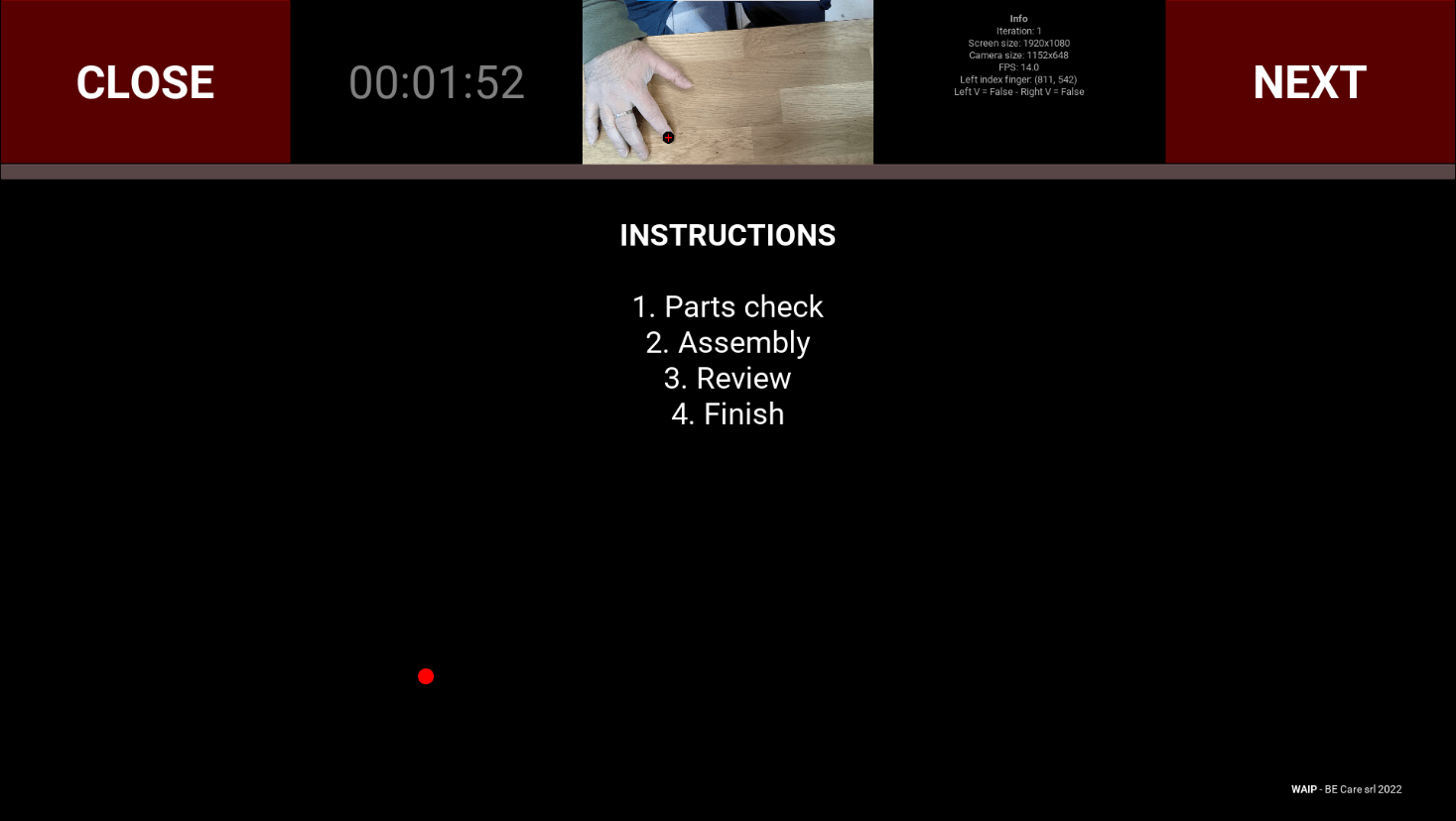
The software prototype simulates a simple production process: environment setup, instructions, part checking, assembly and final check. The calibration system maps the camera’s frame of reference onto the projected interface: a projected cursor follows the operator’s index finger, virtual buttons are pressed by touching the surface, and a few gestures — the V sign with index and middle finger — drive the setup. At the end, an Excel file is generated automatically with the statistics and the photos of each iteration.
What came of it
The prototype proved complete and working. The report also lists the improvements identified for use in production: hand recognition in less-than-ideal light, fine-tuning of the distance between camera and surface, and a projection system with more brightness and a better focal length.
From the lab
The images come from the project’s original documentation.